Measure and mark up 3D models
Determine distances, angles and radii, and add notes
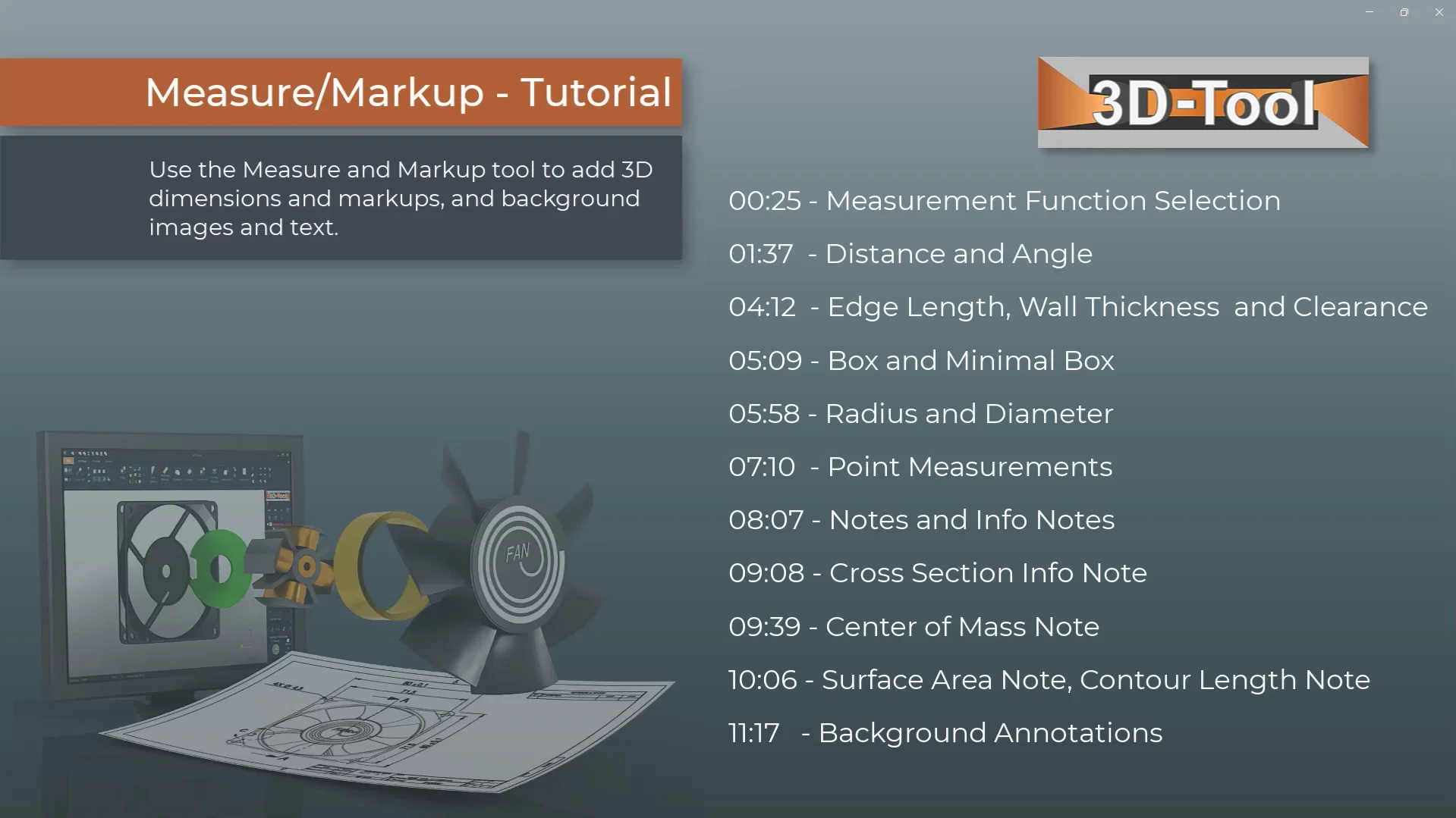
Chapter selection
Video content
- Measurement Function Selection
- Distance and Angle, Edge Length, Wall Thickness and Clearance
- Box and Minimal Box, Radius and Diameter, Point Measurement
- Notes and Info Notes, Cross Section Info Note, Center of Mass Note, Surface Area Note, Contour Length Note
- Background Annotations
Transcript of the video
Welcome to the tutorial on the basics of Measure and Markup. In the following tutorial you will get to know all measurement and note functions. And learn how to insert background images and texts. You select the different measuring functions at the top of the tool. Directly activate one of the recently used functions or select one from the drop-down list at the bottom of a button. We will now use the Distance/Angle function to show you how to measure. Move the mouse pointer over the model and measurement references will be highlighted in blue, then just click to select. Press the ESC key on your keyboard, if you want to start over. A measurement preview helps to select the correct references.
Distance/Angle automatically measures the distance or angle between two measurement references. The minimum distance in space is measured. Between points this is not always the desired result. When measuring points to edges and surfaces, the minimum distance depends on the orientation of the edge or surface. Better for determining distances is therefore to measure between parallel edges and surfaces. If edges and surfaces are not parallel, an angle is measured. If you only want to measure distances, use the Distance function. This disables angle measurement. Only measurement references are offered that allow distance measurement. Distance in X, Y and Z direction does not measure the direct distance, but the distance along the selected direction in the coordinate system. The following two measurements are made for better understanding.
Edge Length measures the length of straight edges and lines. Wall Thickness measures the thickness of the material perpendicular to the surface at the mouse pointer's position. Clearance measures perpendicular to the surface at the mouse pointer's position the distance to the next surface.
Box measures the extent of a part or model along the X, Y and Z axes of the coordinate system. These are not the real dimensions for parts lying obliquely in the coordinate system. To get their exact dimensions, the so-called Minimal Box needs to be calculated.
Radii and diameters can be measured in two ways: automatically or manually by selecting 3 points. In most cases, the automatic measurement should find the desired circles and arcs. These values are the X, Y and Z coordinates of the circle center. The measurement by three points enables the measurement of circles that are not automatically detected.
Point measurements provide the X, Y and Z coordinates of points for models located at a defined position in the coordinate system. Here, the coordinate system is displayed in the view. It is possible to measure edge points, free points on surfaces and centers of circles.
Use the note functions to attach any text as well as special part information. Model Info Note provides information on dimensions, material, weight, volume and surface area for the whole model or individual parts. Materials are specified in the Model Info tool. Volume and weight are only accurate for defect-free, closed bodies.
Measure and Markup also provides information about cross sections. For sectioned parts the Cross Section Info Note calculates the cross section area and the length of the section line. Center of Mass Note calculates the center of mass for the complete model or individual parts. The note can only be created if a material has been assigned to each associated part. Surface Area Note uses a tolerance angle to define a surface area and to calculate its size. Contour length Note calculates the length of contours. Automatically for selected surfaces or manually by selecting individual edges.
Use the background annotation to add graphics and text to the background of the model, such as a company logo. Place pictures and texts in the upper left area of the display, as their size and position depend on monitor resolution.