VPE and Digital Mockup
Today, development and construction are hardly imaginable without 3D CAD software. Before committing to prototypes, and before assembly and production, Virtual product development (VPE) enables:
- Feasibility studies and early error detection
- Verification of ergonomics, design and completeness
- Evaluation of space requirements and serviceability
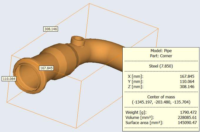
Models published with 3D-Tool are available to everyone. The 3D-Tool FreeViewer also supports professional measurement and analysis functions and allows the whole team to participate in the so-called Digital Mockup (DMU).